Some further info and parts list.
Here are the parts that we used in this operation. We bought off Amazon, shopping around you can probably find them cheaper and we are not an Amazon affiliate.
1 each Stepperonline MMRV30 5:1 dual axis Gear Speed Reducer. $50.00 when we bought it 2/24//2024 Gearbox at Amazon
2 each Stepperonline single output shaft for MMRV30 Gear Speed Reducer. $13.00 each, $26.00 2/24/2024 Output shaft at Amazon
1 each Stepperonline Shaft Sleeve Adaptor, 11mm to 8mm for MMVR30 Gearbox. $9.99 on 2/24/2024 Sleeve adaptor at Amazon
2 each uxcell 25 tooth roller sprocket B Type, 25 chain, 1/4"Pitch, 8mm bore. $11.59 each, $23.18 2/24/2024 25 tooth gear at Amazon
3 feet B Type, 25 chain, 1/4"Pitch, 8mm bore. $9.27 each 2/24/2024 #25 roller chain at Amazon
#25 Roller Chain master link (5 Pack) $5.99 2/24/2024 #25 roller chain master link at Amazon
The output shafts will have to be center drilled to accept the gear axles. They are 8mm which is close enough to 21/64" that worked for us. We used a lathe to drill the holes approximately 12.5mm or 1/2' inch deep but a drill press will work. We then drilled and tapped 2 each #18 or .1695 (since these are SAE screws I didn't convert to metric. It's approximately an M5 screw so 4.2mm tap drill) holes at 90° and tapped for 10-32 set screws.
Next we filed approximately 12.5mm or 1/2" of the drive gear axles flat to fit into the output shafts.
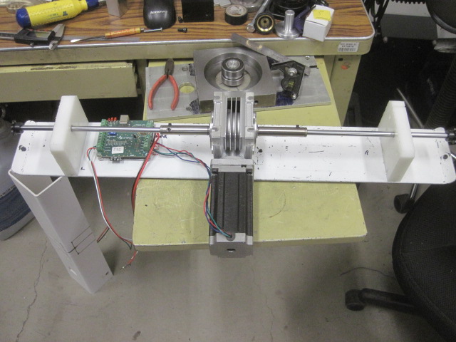
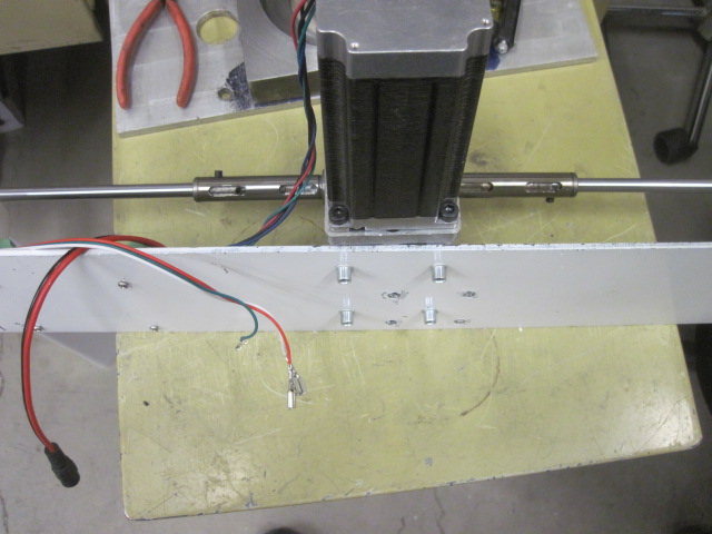
Mounting the gearbox was pretty straight forward. We found center between the two plastic end blocks and spaced the mounting holes off from the paperwork supplied with the gearbox. As noted in the pictures above, we used nutserts to mount it but a better option is to just use bolts from the bottom with nuts on top as there isn't enough rooms for the allen wrenches on top.
Next the holes for the drive shafts will need to be relocated in the plastic end blocks. We butted the bearing housing of the gearbox up to the base plate which put our holes 44mm or 1.73229" back and 57mm or 2.24409" up. Your locations will probably vary, but that is a general starting point.
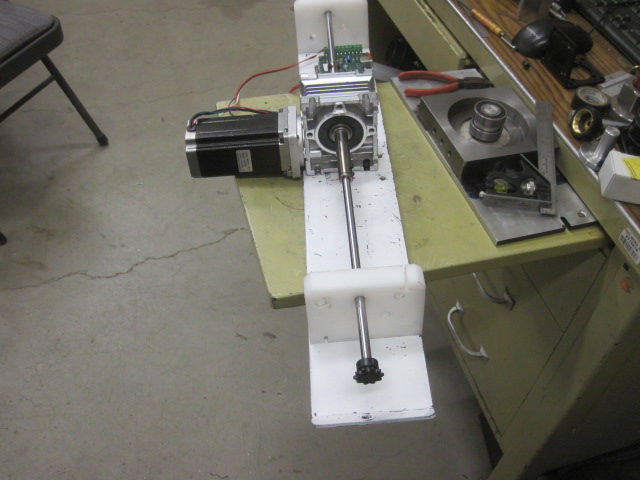
Once that is done place the drive shafts throught the plastic block holes and secure to the output shafts. We put a drop of Loctite on the output shafts where they enter the gearbox and on the drive axles where they enter the output shafts. We then changed the drive gears from the stock 11 tooth gears to the 25 tooth gears. This required adding about 5 links on each side. Our spacing is 2.8" or 71mm out from the outer edge of the plastic end plates. This cut the open close cycle from around 8 minutes (sorry, don't know what minutes are in metric.) to just about 3 minutes.
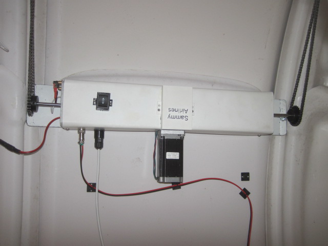
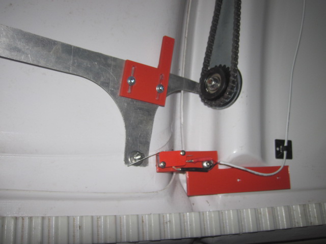
Next we trimmed out the access holes for the bottom and top for the gearbox. We 3d printed a raised cover for the gearbox (Upside down in the photos) and a raised switch mount. The leads off the manual control switch would other wise hit the left side drive axle. An option would be to remote the switch down where it would be more convenient during normal operation and put a cover over the hole.